This work was completed as part of course requirements for MIT Course 2.720: Elements of Machine Design. Professor Marty Culpepper is the instructor. My teammates were Seiji Engelkemier, Hadeel Abdo, Jonathan Sampson, Kaleb Blake, and Qiyun Gao.
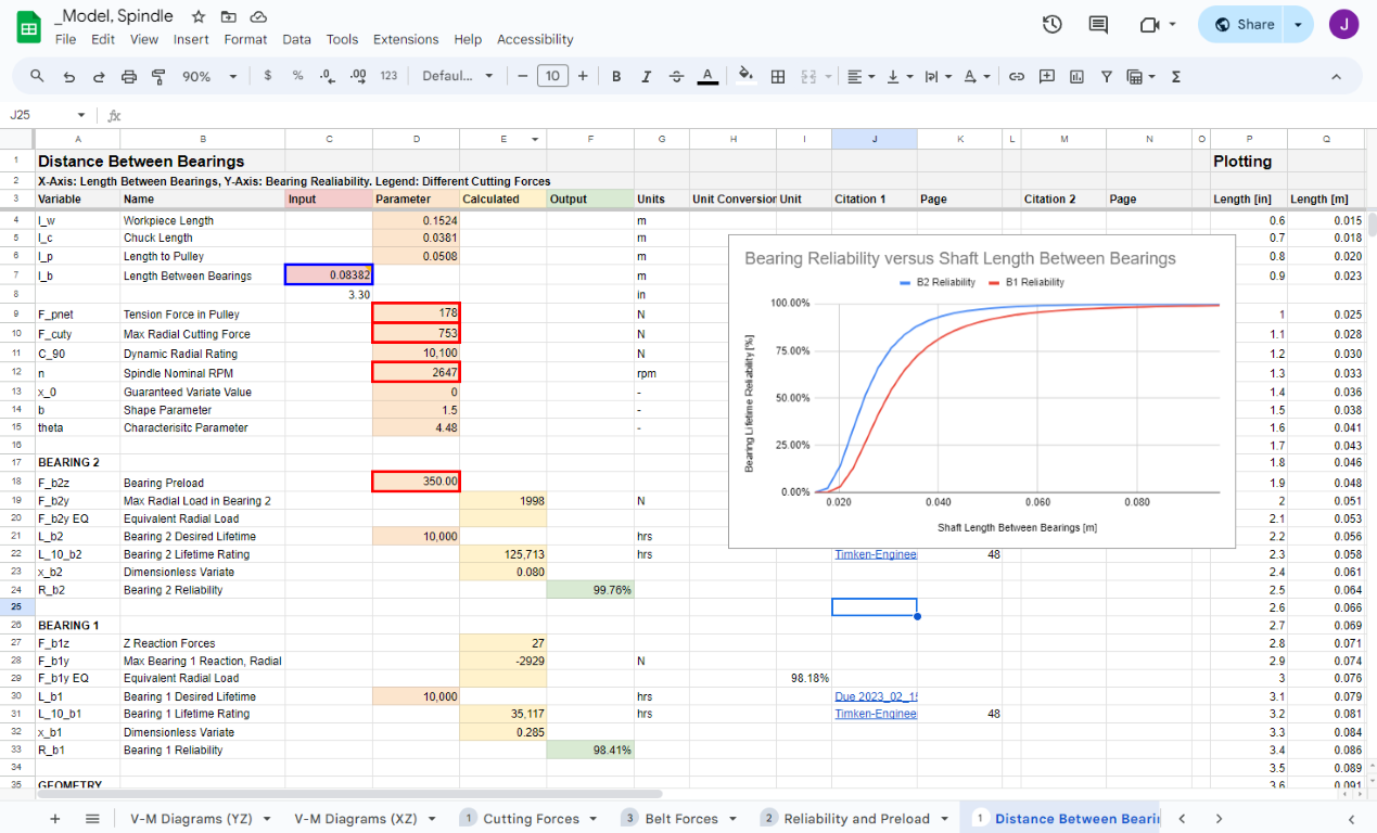
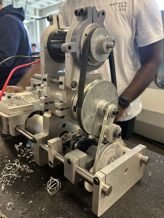
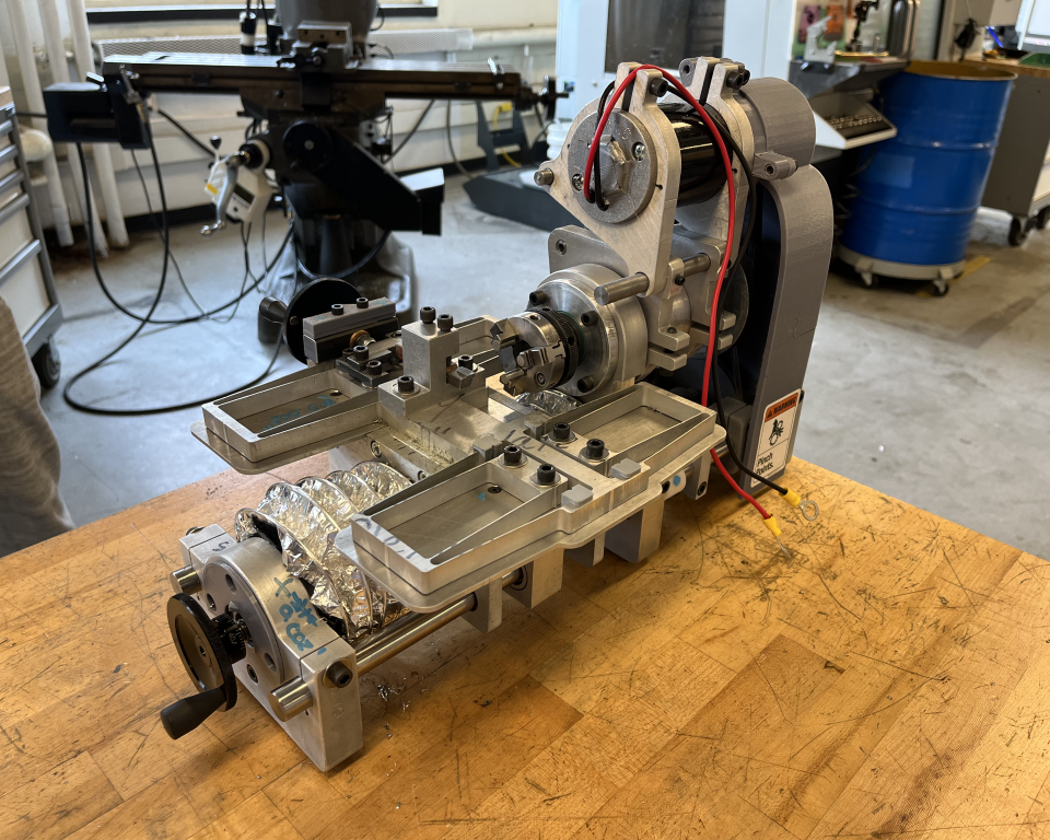
2.72: Elements of Machine Design is a notoriously challenging test of mechanical aptitude, requiring students to design and construct a desktop lathe which meets a litany of self-assigned functional requirements. For this course, I had the role of a “modeling guru,” meaning I was responsible for compiling many of the governing mathematics into scripts and spreadsheets that would inform our design decisions.
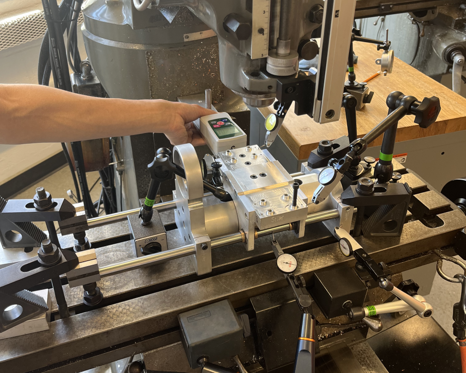
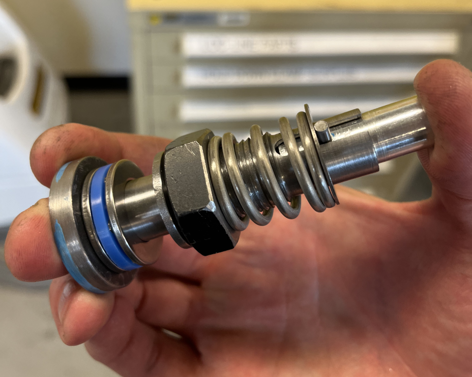
At the beginning of the semester we tear down the lathe from the previous semester and scrutinize every aspect of their design. However, this exercise only scratches the surface of what's to come later in the course as we design our own lathe.
The first major deliverable for the lathe was the spindle which was comprised of spindle shaft, spindle housing, and tapered roller bearings. Considerable effort went to the calculations of bearing lifetime, shear and moment diagrams, error budget, thermal expansion, and much more.
After a few hours of careful turning and milling, we inspected our spindle for runout, thermal expansion, and stiffness to determine whether we had met functional requirements.
Crunching numbers, making parts, inspecting parts, remaking parts, and revising functional requirements quickly became a normal routine.
Having years of prior manufacturing experience, I was keen on focusing on my role as the modeling guru. I wanted to continue improving my mathmetics and modeling. Still, I found myself doing a large amount of project management, FEA, testing, CAD, machining, fabrication, and metrology.
Following the spindle, the next major deliverable was the cross slide, which consisted of a leadscrew, leadnut, and a large flexure. As always, sketching the design and writing out some design considerations was a helpful first step when approaching the modeling.
As before, our modeling was only as good as our manufacturing. Multiple test pieces were cut to characterize the performance of the waterjet before settling on the final design and cut parameters.
Although I had taken 2.s793 (now 2.147) Design of Compliant Mechanisms, Machines, and Systems in the previous semester, this large cross slide flexure reinforced the unique capabilities of flexures in precision machine design.
The second-to-last deliverable was the rest of the lathe. In order to finalize the build, we employed a Homogenous Transformation Matrix (HTM). This clever tool allowed us to take a global view of the lathe structure, determining how cutting forces and thermal expansion propogated to each of the subsystems in the lathe.
The HTM was easily one of the most challenging aspects of my role as a modeling guru. Fortunately, through the support of the team and after a very long night of work, the HTM was ready for our checkoff.
The final deliverable was our self-selected graduate component: A mechanical autofeed. The modeling considered the specific cutting energy required for steel and aluminum as well as the range of surface speeds for materials of different diameters.
Though we had worked hard to reach this point, our expectations were low for the final competition. We were second to compete, but as each team stepped up, it became more apparent, we would be the winners. This accomplishment was like a cherry on top of a challenging semester.
Check out a video of the competition below, including our awesome autofeed mechanism. If you're watching this, I hope you can forgive my carelessness with some sharp aluminum chips.